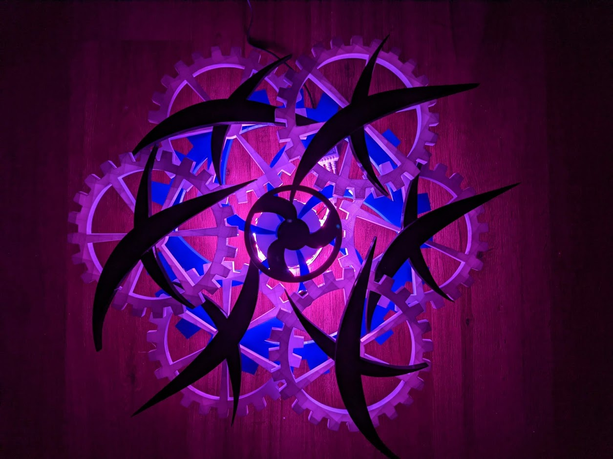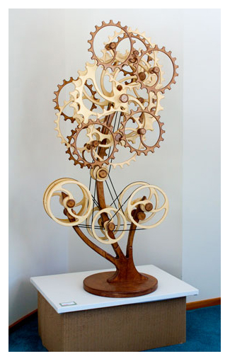

Kinetic Sculpture - “Mindful”
CompFab Final Project
Please be patient as this page takes a while to load since there are many high quality photos and gifs on this page!
Jayleen Li
Introduction:
Description: Building and exploration of motor controlled kinetic sculptures as well as light and its interaction as an aesthetic to kinetic sculptures.
Links:
Motivation:
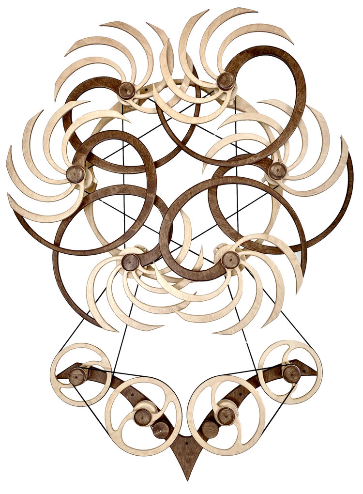
I was inspired by David C. Roy, a famous artist who specializes in making kinetic wood sculptures. All of David C. Roy’s sculptures do not use any electricity or motors and rely on springs and forces to move. I wanted the piece to move without any involvement so I tried to use electric motors and gears to power the sculpture. I also wanted to incorporate LED lights if possible. I used his designs as inspirations but not his style of using physics to power sculptures.
There are a lot of things that qualify as kinetic sculptures. Out of the designs I saw online, I liked David C. Roy’s layered approach and decided to imitate it. I wanted the sculpture to be large enough and function as a wall decorative piece.
Here are the three main sculptures (all from David C. Roy) that I drew inspiration from for the main design.
Variation II Sun (David C Roy)
Design Direction:
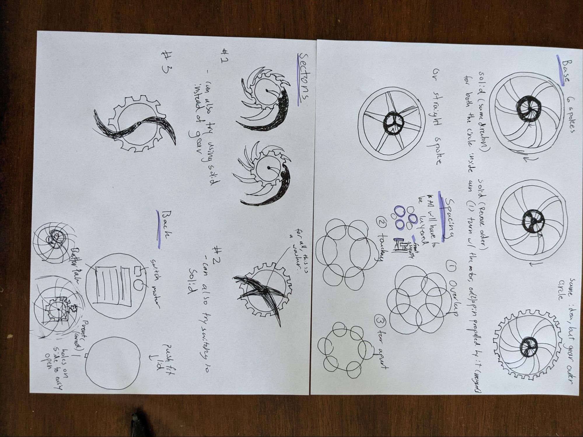
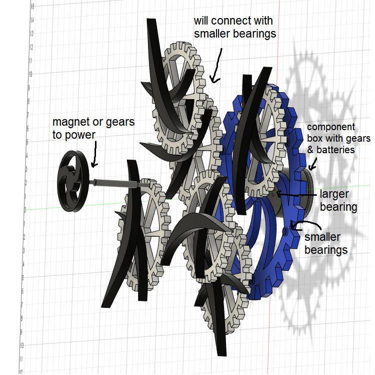
The idea was to have some sort of structured shape (which are the gears) and integrate them with organic shapes.
Closely following David C Roy’s Variation Sun piece, I wanted to have a design with six smaller circles rotating on a larger circle. But instead of basic circles, I went with gears. The larger circle I called the base and the smaller circles I called sections. I originally had a few ideas for both the base and sections and decided which variation I wanted as I actually designed the parts in Fusion 360.
The color scheme for the sculpture was black, white, and blue. The black shapes therefore would pop out.
Approach (not in order):
Materials used:
Modeling and Animations:
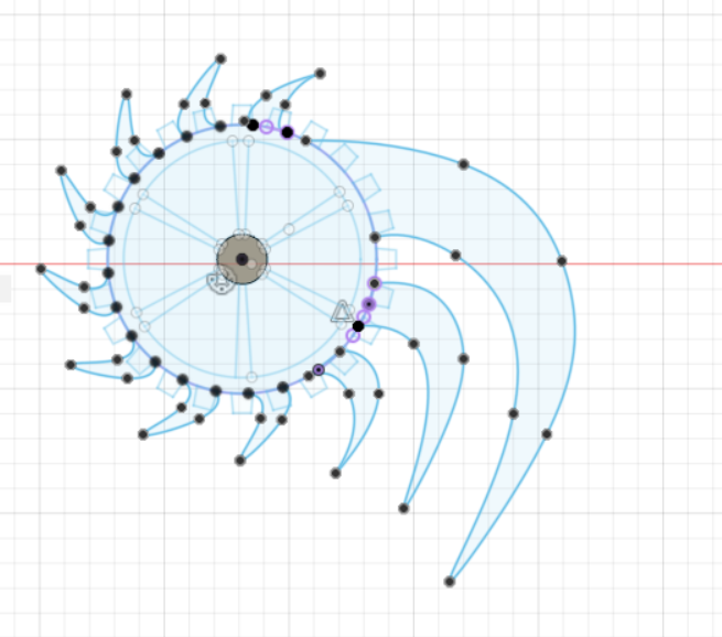
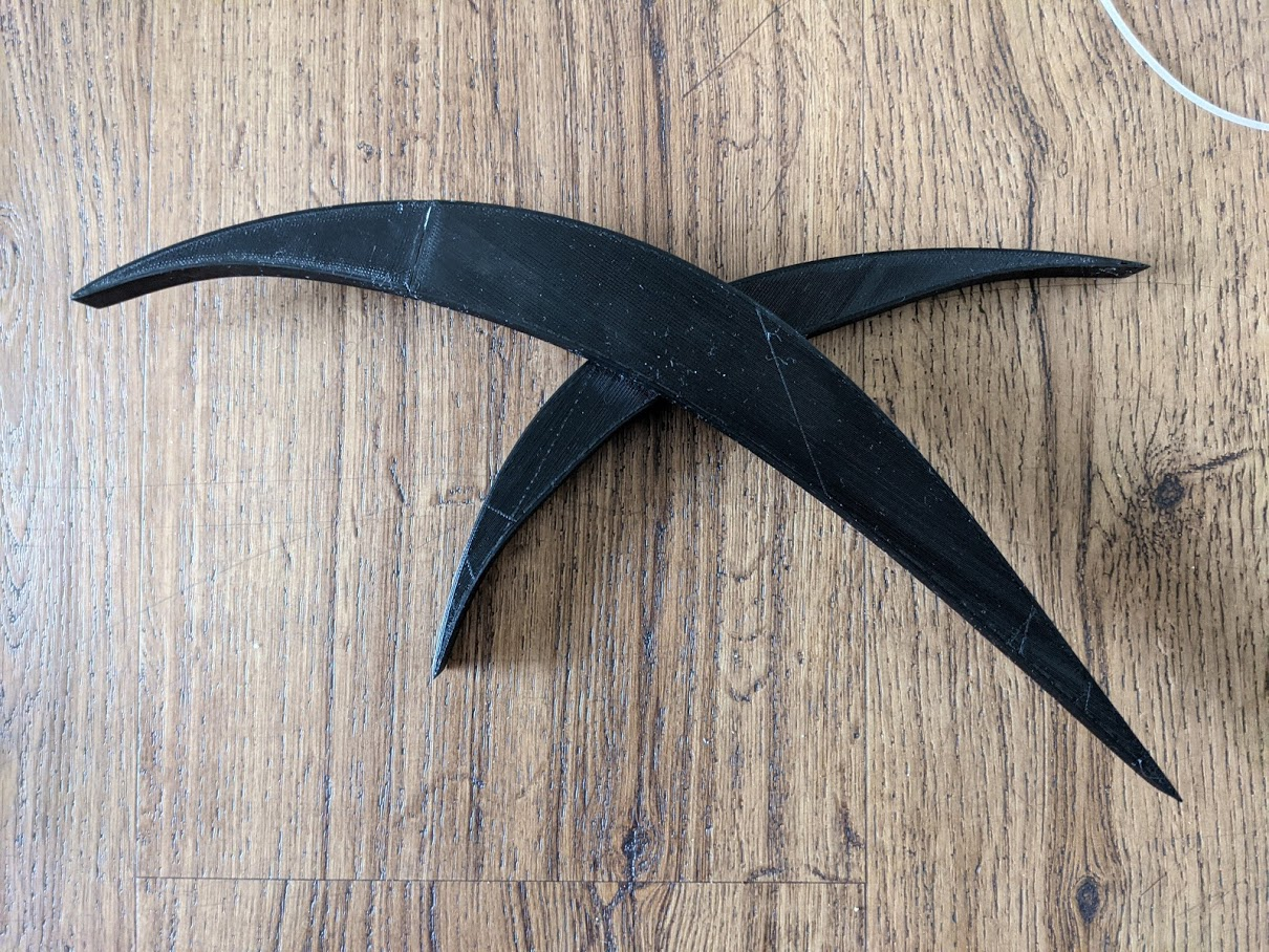
I started with idea 1, the spiral design. It was really hard to get the shapes I liked so I gave up with this idea and decided to go with idea 2, which I called the “wing” design.
Spiral Variation
No matter how I made the curves, I couldn’t get a shape that I liked. 😔
Wing Variation
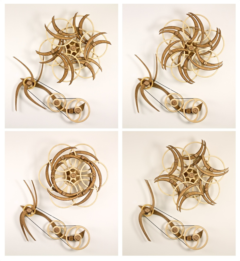
Here are some animations I created in Fusion360 to visualize how I wanted the sculpture to move.
What if the larger wing is dynamic while the smaller wing is static?
Dynamic in this case meaning free hanging.
What if both wings are dynamic?
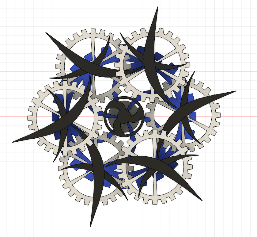
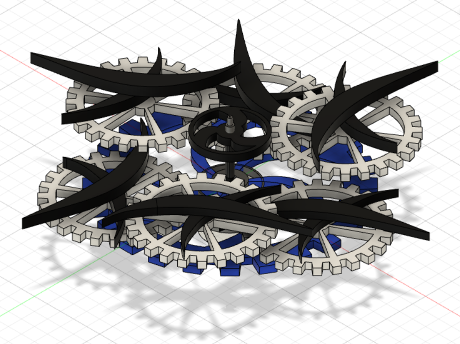
Final animation with colors. This is the “both wings are dynamic” design.
Explore the model!
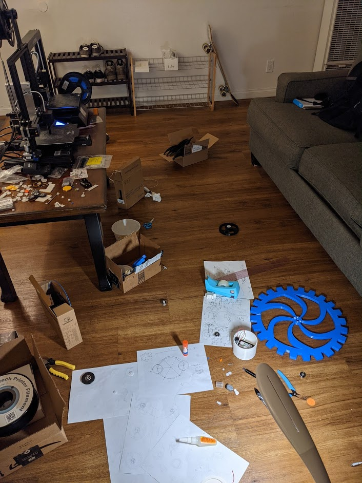
Printing, Assembly, and more Designing:
Creating the actual sculpture was an iterative and explorative process. I wasn’t sure how I could fit everything together until I worked more on the individual parts. I printed, assembled, and designed parts all at the same time, creating additional parts when needed.
The final sculpture is massive. It’s final dimensions are:
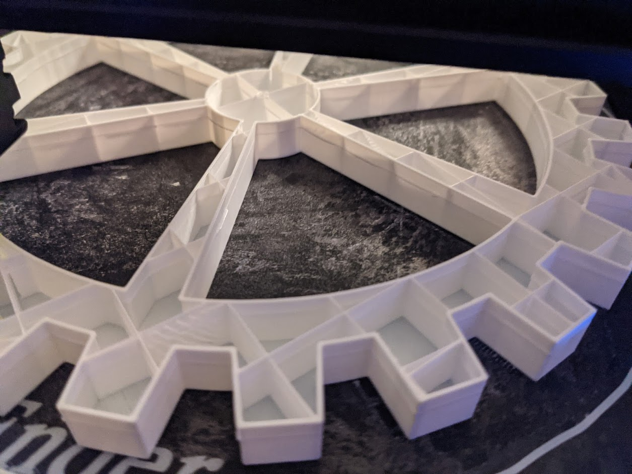
Blue base gear = 16in (406.4mm) diameter
White smaller gear sections = 8.5in (215.9mm) diameter
Total = 24.5in x 24.5in x 8.5in (approx)
622.3mm x 622.3mm x 215.9mm (approx)
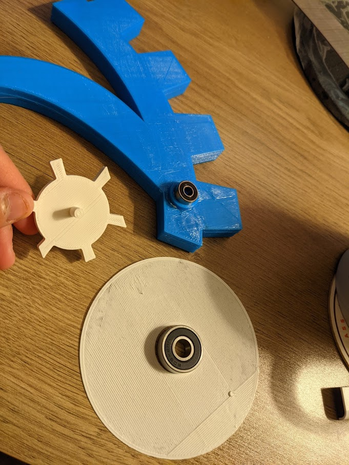
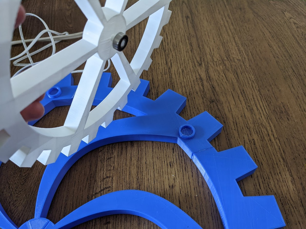
Test fit
I first did some test fit tolerance prints for push fit design.
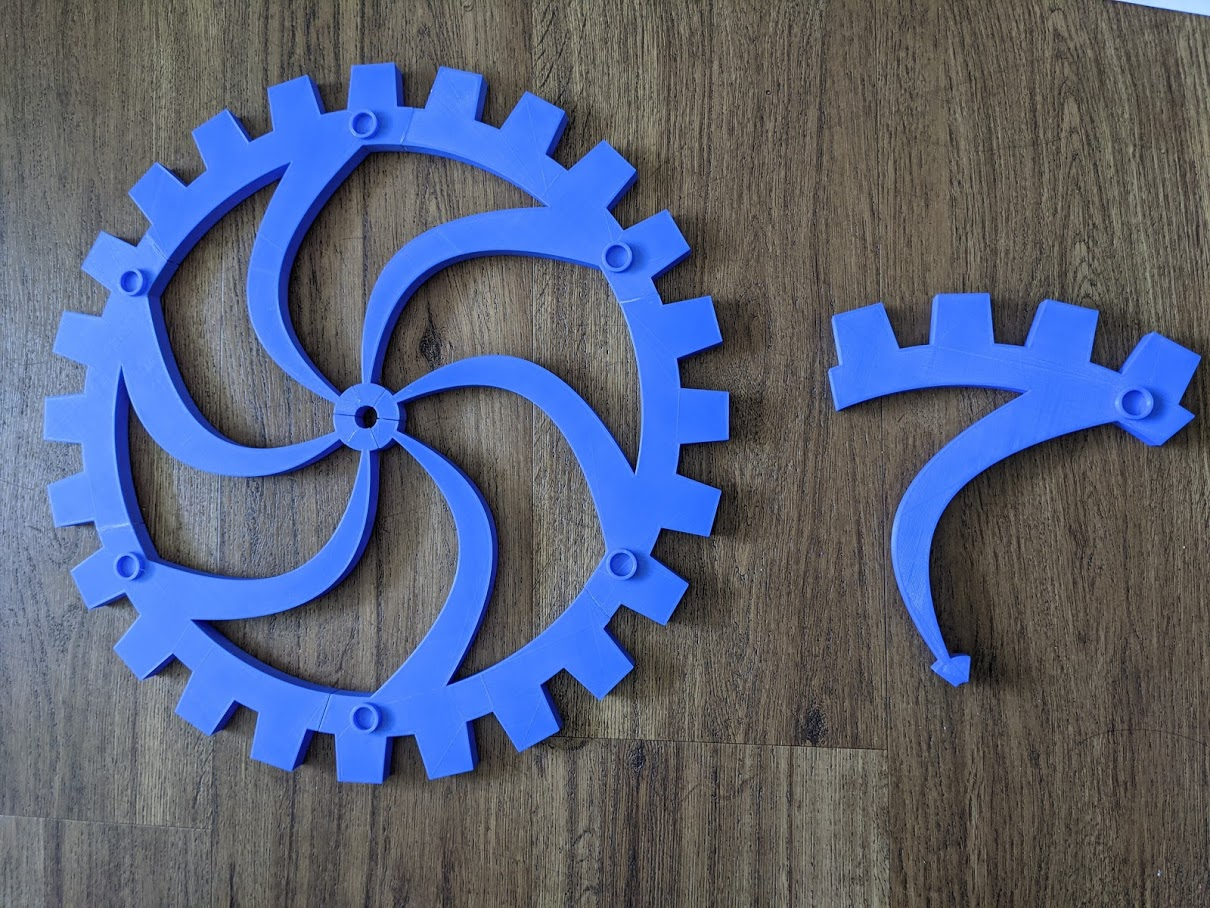
Printing and splitting
Many of the parts had to be split into multiple parts because they wouldn’t completely print on a 3D printer bed. For example, the blue base gear is actually made of six separate parts and the black wings are made of two separate parts. As with the other components of the sculpture, everything was attached using gorilla glue.
Gearbox
The gearbox was the most challenging part of this project.
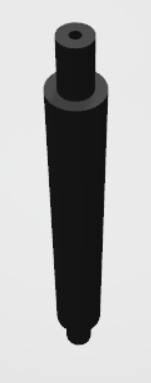
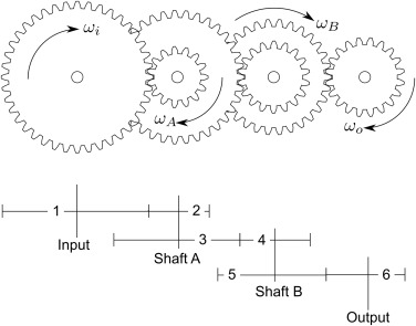
I first experimented with the gears and arranged them like so to slow them down as DC motors spin extremely fast because of their minimum power requirement. I got ideas of how to slow down the gears from this video. The idea is to have compound gears rotating interchangeably from large to small gears causing a slowdown for each successive gear. The orange gear would be connected to the base rod (pictured).
Compound gears rotating interchangeably example.
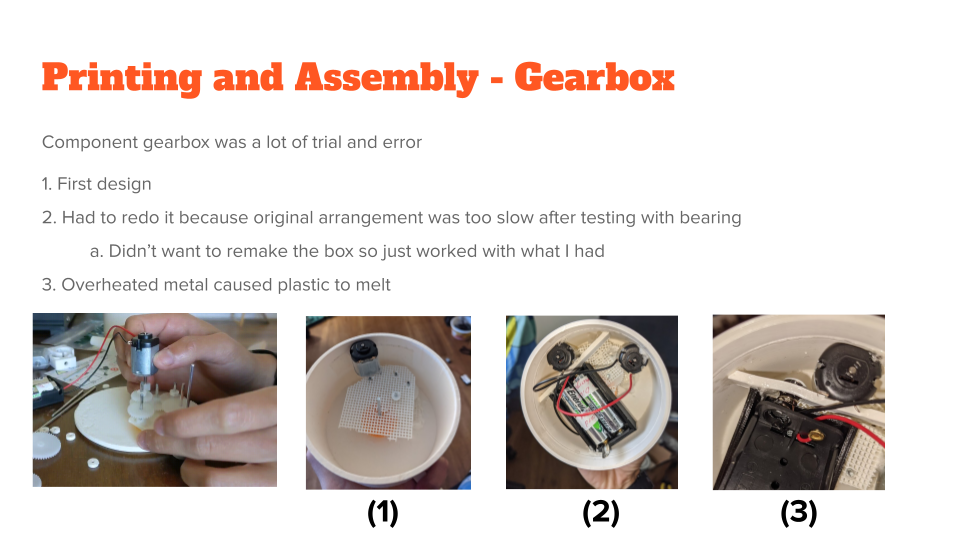
(1) I secured the component in place using part of a piece made from a previous gcode assignment with gorilla glue. I also made small spacers to hold gears in place so they wouldn’t move. I added a part to hold the batteries for the motor. In this stage I realized the motor was taller than I expected so I printed a small ring to extend the height of the component box so it could enclose everything together.
(2) However, after trying this design out with a test rod and bearing I noticed the rod was spinning at a very slow rate. Instead of redoing the entire component box, I removed some parts and readjusted them. I also placed another motor inside the box instead of removing the other one. I attached the real base rod into the component box and placed a bearing in the front.
(3) Then a tragedy occured. I had a short circuit somewhere causing a hole to burn through the PLA holding the battery pack. To fix this issue I cut out the melted circuitry and used my 3D pen to fill in the melted hole.
(4) After assembling the push fit lid on the back of the component box and wiring the switch I realized another issue. If the switch is popping out of the component box on the same side that would be attached to the wall, how would I attach the box to the wall?
(5) No problem, I can just make a small part that would attach to the back of the box with a small hole for the switch so the back would be flat again. However, I then realized that I wouldn’t be able to flip the switch if it was attached to the wall.
(6) I figured that I would use my 3D pen and burn a hole in the side of the box so I could have the wires and switch outside the box. So now that’s why the switch is outside the box!
Here is a video of the component box at stage (4).
GIF showing the push fit part of the component box in the early versions of the box.
It’s all coming together
After I figured out the gearbox, I was able to finalize how I could imagine all the moving parts fit together. Here is a diagram illustrating that.
Weight Distribution
As I printed more and more pieces I realized I had another problem that arose. Weight distribution. All the weight of the sculpture was towards one side of the sculpture.
At this point I had printed every large component except the smaller white component gears. To try to alleviate the distribution, I changed the Cura settings so the gears would print at 5% infill and that the shell would be 0.6 mm.
The resulting gears were indeed light but it was also fragile. The force I used to put the pieces into their respective bearings caused some of the gears to crack internally and thus were not perfectly straight. I fixed these as best I could with gorilla glue or my 3D pen to reshape the plastic.
Because I knew the base rod would have to carry all the weight I printed it at 75% infill to keep it sturdy. Unfortunately it is not enough to support the entire sculpture. I do not have a scale so I have no idea how heavy the sculpture is. But definitely the torque is not balanced somewhere.
So instead, “Mindful” now resides as a floor decorative piece.
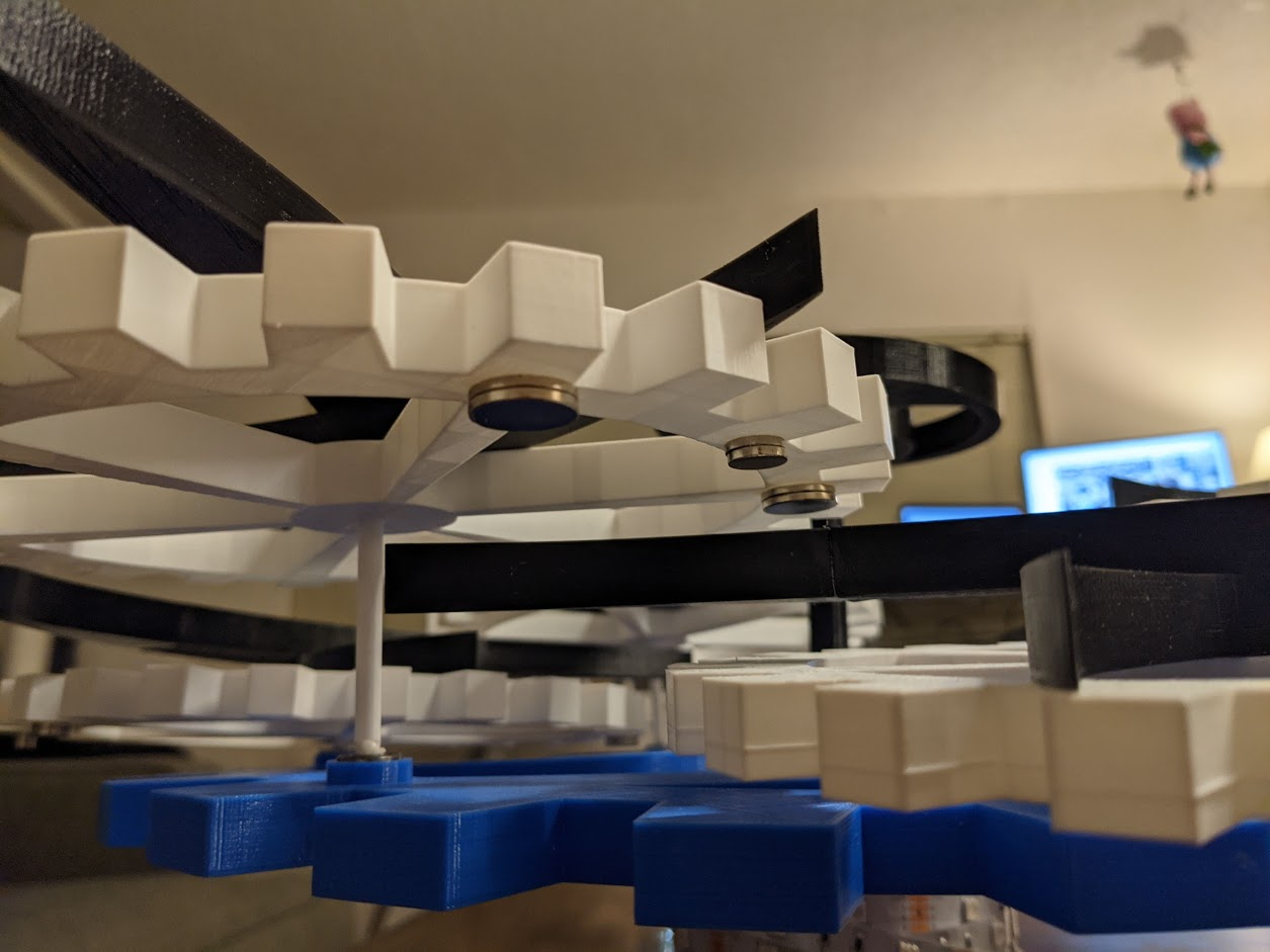
Attaching weights
Originally I was planning on using the magnets as weight to keep the smaller sections steady as the base rotated. The sections would take advantage of gravity to achieve the movement I was imagining.
But since “Mindful” is now on the floor, gravity is affecting the sculpture in another direction. To alleviate the problems found in the weight distribution I used magnets instead to try to steady the smaller gear components so they would not intersect with the other parts as easily.
Movement simplification
Originally I wanted to have the topper part rotate in an opposite direction as shown here. This is why I made the center of the topper large enough to fit additional gears to reverse the spin direction. But because the sculpture became a floor piece, incorporating the parts to reverse the direction would not add much value to the sculpture so I decided to exclude it from the design and directly attach the topper to the rod.
Video and Closer Look
Learnings and Reflections
Full reflection here.